Eurobox case for AVR-NET-IO
Description
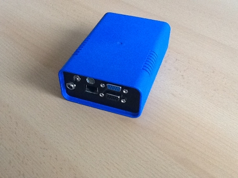
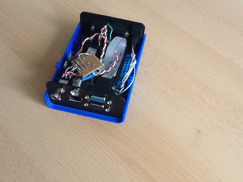
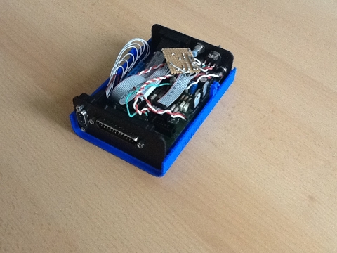
For presentation purposes and because it looks nice, I put my AVR-NET-IO board in a Eurobox. To give something to everybody that interested in it, I made this little documentation. I also documented circuit diagrams and drawings of frontside and backside of the case.
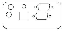
On the front, there is a switch for switching between normal use and programing. Next to that is the status LED which shows the operation of the board. Switching on and off is done by pluging in and removing the power cable (connector under the switch). The screw terminal has been removed but the rectifier is still in use. The blue DSUB connector is the ISP interface. The one under it is for communication with the ATMega. Of course, the network connector is accessible too.
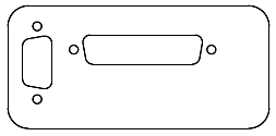
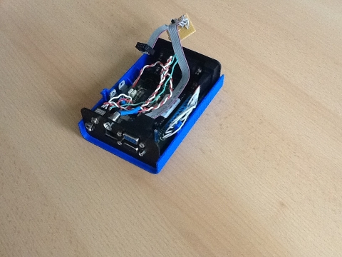
The backside has a DSUB-25 with the connectors from the back of the AVR-NET-IO. I have to say, that the connector is a little bit higher. It is not the real board connector, because the case is a little bit longer then the NET-IO board. The DSUB-9 at the side is connected to the screw terminals at the side of the board. ARef is not connected.
Images
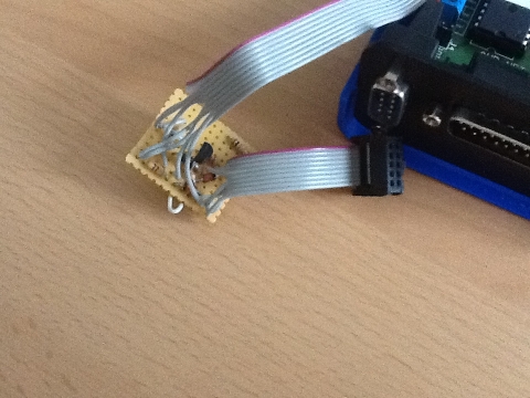
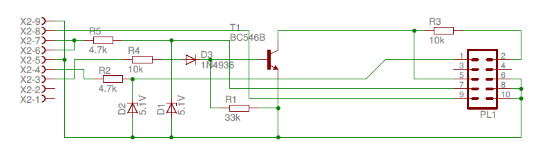
ISP adapter
I created an serial interface adapter for the boards ISP interface, to be able to program the micro controller, while the board is in the box. The following image shows the circuit diagram.
Front and back side
The drawing for the frontside is, compared to the images, changed a little bit. I switched the places of LED and switch. The schemes are available as FreeCad drawings for download, right here.